|
|
|
|
|
|
| Re: I finally figured it out! [message #16691 is a reply to message #16548] |
Thu, 16 February 2012 20:14   |
 cassent5150
Messages: 341
Registered: August 2009
|
Senior Member |
|
|
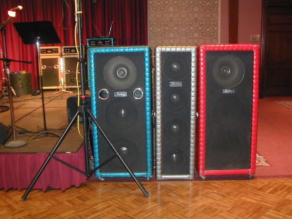
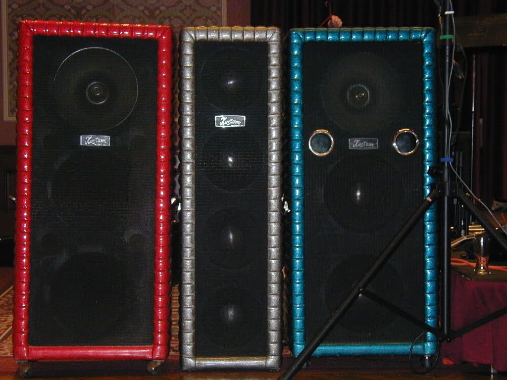
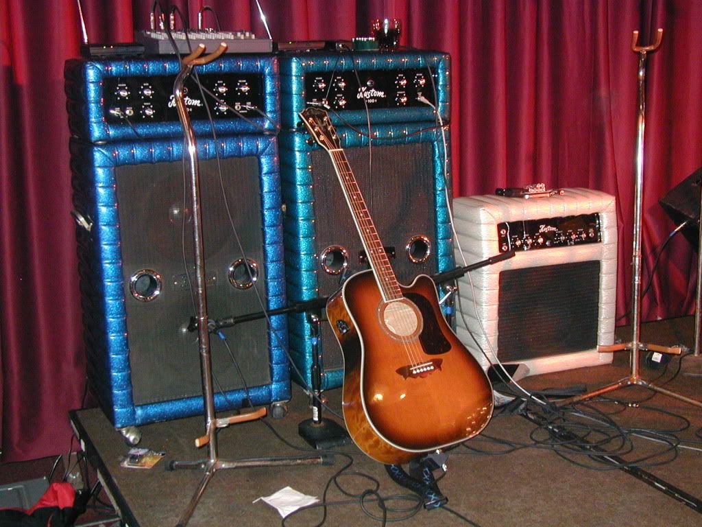
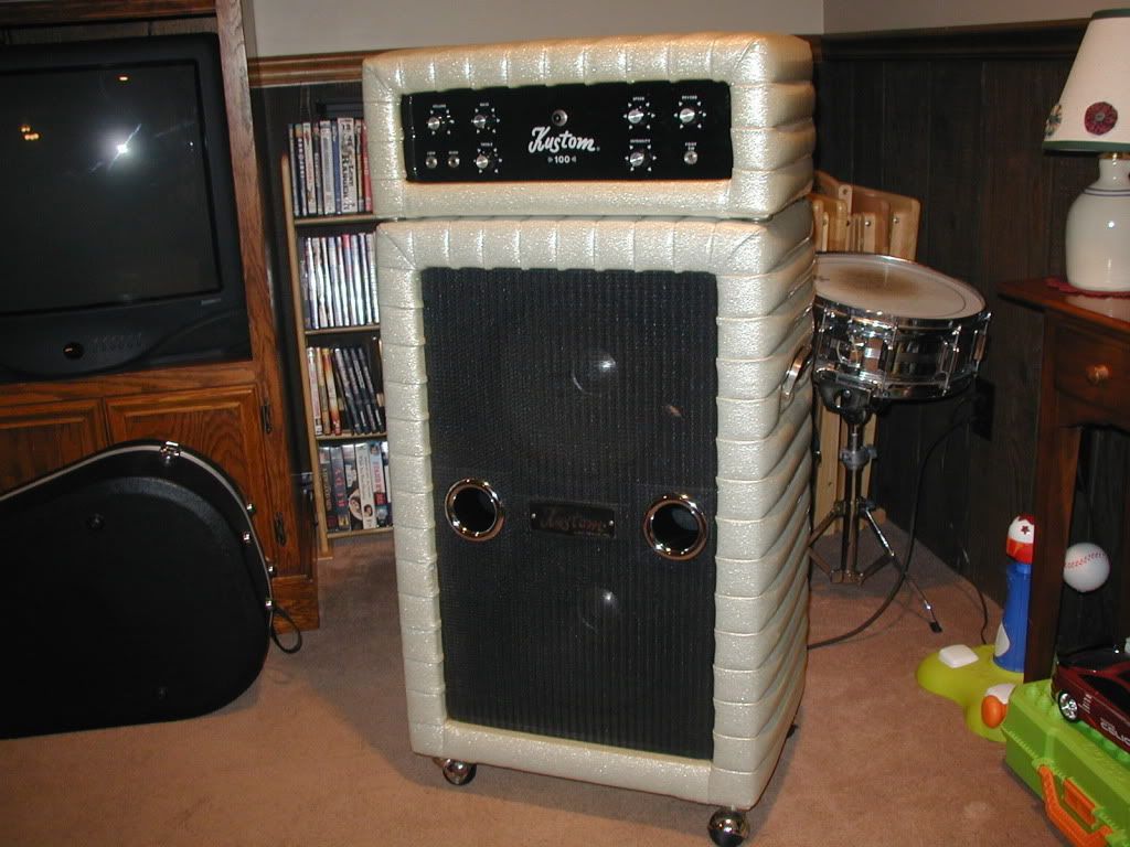
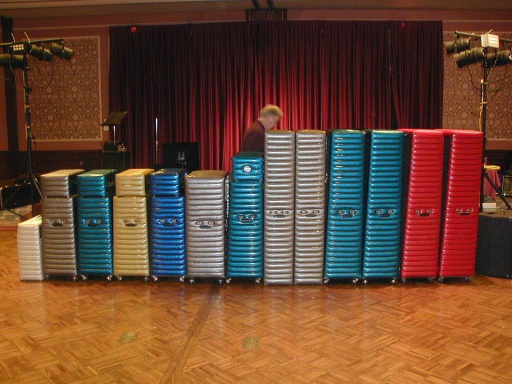
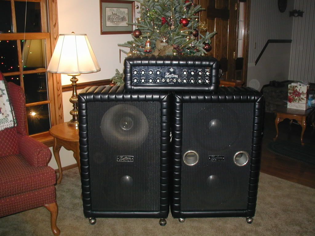
Far out!!! Good looking bunch of color Kustoms. I dig the Black A-4 on top the two 215-B's tooooo!!! Nice, I must admit, looking at and playing them is a whole lot more fun than working on them, but I love to do both.
Steve C
Steve C
|
|
|
|
|
|
|
|
| Re: I finally figured it out! [message #16697 is a reply to message #16693] |
Fri, 17 February 2012 12:33   |
 cassent5150
Messages: 341
Registered: August 2009
|
Senior Member |
|
|
I dont see why you can't run both cabs on that A-4 if the cabs are 8 ohm each. The A-4 will run at 4 ohms, at least my A-1 will and I don't know there to be a difference in the two models as far as the main output section. The literature on the A models show it sitting on top of 2 cabinets and as I recall the speakers in them were 16 ohm making each cabinet 8 ohms which would in turn give you a 4 ohm load when your running both cabinets. If your playing guitar through them, the siren might have to go, but bass should work fine. I believe they had a 10 uf cap in the + line of the siren as a crossover. The siren cab can double as a PA main, allthough I found them to be not very efficient, but it takes a little more juice to get them out there. I've done a show with my pair of 2X15 siren cabs and they worked fine as mains with a 8 channel, 500 watt (MONO) Fender PA Head. I've used the 3X15 PA cabinets normally, but they tend to block the view of the band in most clubs cause the stage area is usually small and thats where those 2X15 siren cabs can be very useful to keep that cool Kustom tuck and roll mojo happening.
Well, thats my 2 pennys worth!! Steve C
Steve C
[Updated on: Fri, 17 February 2012 12:35] Report message to a moderator |
|
|
|
| Re: I finally figured it out! [message #16698 is a reply to message #16697] |
Fri, 17 February 2012 13:31   |
C4ster
Messages: 686
Registered: June 2001
Location: Mukwonago, WI (Milwaukee...
|
Senior Member |
|
|
Sorry, each D130F is 8 ohms, not the cabinet. I would end up with 2 ohms if I ran both cabs. I am going to reduce the emitter resistors in the amp from 1 ohm to 0.5 ohms and see what happens. With the 1 ohm resistors, the amount of feedback to the differential pair will get too large if you run the speaker load down to 2 ohms. But a Sunn SA21 power amp that I have uses 0.33 ohm resistors and is 2 ohm stable. This gives me the idea that the 0.5 ohm resistors would bring the feedback into line at 2 ohms as the 1 ohm resistors at 4 ohms. The net result may be more power than was originally designed. The siren cab has the crossover cap in it but I'm not a fan of the horn for guitar. Way too bright. I will replace the siren with another D130F.
Conrad
|
|
|
|
|
|
|
|
| Re: I finally figured it out! [message #16702 is a reply to message #16699] |
Fri, 17 February 2012 22:50   |
C4ster
Messages: 686
Registered: June 2001
Location: Mukwonago, WI (Milwaukee...
|
Senior Member |
|
|
If you are referring to posting pictures, you need a site that you can store or share your pictures with others. One is photobucket but I would suspect Facebook would work also. Then you need click on the icon above that says "insert an image" and link the photos to the pictures on your shared site. The pictures appear mysteriously. Here is the link for the first picture. http://i1136.photobucket.com/albums/n499/C4ster/PC170021.jpg
As far as the impedance issue is concerned, I thought about the series connection. That would yield me a lower power, probably 60-65 watts, which would be more controllable and less obnoxious in a room smaller than the Astrodome but that's not the issue. I need to try this just because I thought about it. Now I have to prove it (or not). Besides, if it does work, then I could work out the same configuration in my son's K200-B1 for bass. In that case, the more power the better. Just for reference, the Sunn SA21 amp is 140 watts @ 8 ohms, 200 watts @ 4 ohms and 300 watts @ 2 ohms. That would be a kick for a Kustom.
Conrad
|
|
|
|
| Re: I finally figured it out! [message #16705 is a reply to message #16698] |
Sat, 18 February 2012 10:53   |
 cassent5150
Messages: 341
Registered: August 2009
|
Senior Member |
|
|
Isn't that dangerous for the output transistors to run at 2 ohms? How does lowering the value of the emiter resistors control the heat created at 2 ohms in the output transistors? I'm curious as to how that would effect the operating temperature of the transistors in that situation. Seems there would be a lot more heat on them. Thanks Steve C
Steve C
[Updated on: Sat, 18 February 2012 10:59] Report message to a moderator |
|
|
|
| Re: I finally figured it out! [message #16708 is a reply to message #16705] |
Sat, 18 February 2012 13:05   |
C4ster
Messages: 686
Registered: June 2001
Location: Mukwonago, WI (Milwaukee...
|
Senior Member |
|
|
The issue with the 1 ohm emmitter resistor is that the voltage drop across it is sent to the differential pair as negative feedback. The lower the speaker load, the greater the feedback voltage. This can cause the system to become unstable. I will admit that the output transistors are a 2N3055 equivalent so to address the added current, I would need to replace them with MJ15022 transistors which have a much higher power rating. I would expect to have to experiment a little to get the results I want but it still is an experiment. I think the power transformer is big enough to handle the added load, but the voltage may be low. I need more than 40 volts on the rails and the A4 only has 34 Volts available.
Conrad
|
|
|
|
|
|
| Re: I finally figured it out! [message #16710 is a reply to message #16709] |
Sat, 18 February 2012 16:55   |
C4ster
Messages: 686
Registered: June 2001
Location: Mukwonago, WI (Milwaukee...
|
Senior Member |
|
|
I'm not necessarily looking for more power, I just would like to run both cabs on occasion. But along with the lower impedance capability, the power might go up slightly. The numbers I cited for the Sunn amp are just for comparison. I would hate to use the A4 for bass. What a waste of the effects. The series connection would be the easiest and fastest way to accomplish this. But, I need another JBL D130F for the siren cab. That comes later.
Conrad
|
|
|
|
| Re: I finally figured it out! [message #16712 is a reply to message #16710] |
Sun, 19 February 2012 09:41   |
 cassent5150
Messages: 341
Registered: August 2009
|
Senior Member |
|
|
Just a quick question. I picked up 3 new unused power transformers designed for the 130 watt music man bass amps. I'm getting 88 volts across the rails on them ( I've got one in a 200B-2, K-II lead, and just had a failed rectifier burn up the tranformer in a K200B-1 at my last gig so I put the last one in it. I'd like to try your theory on it, the B-1 that is, I have the .33 five watt resistors and access to those MJ15022 transistors so the question is "would 88 volts be enough"?
Steve C
|
|
|
|
| Re: I finally figured it out! [message #16714 is a reply to message #16712] |
Sun, 19 February 2012 11:45   |
C4ster
Messages: 686
Registered: June 2001
Location: Mukwonago, WI (Milwaukee...
|
Senior Member |
|
|
I wanted to check the schematic and voltages of the Sunn SA21 power amp but I couldn't find them. But if my failing memory serves me, the rails are +/-40 volts. That would yield 28 volts RMS which at 4 ohms would be 200 watts. Now allowing for sagging voltage in the power supply at higher currents I would expect perhaps 300 watts at 2 ohms. The lower emitter resistors do pump out more power to the speakers and less power loss across the resistors. The Sunn has 0.33 ohm resistors. The +/-44 volts may upset the biasing in the rest of the amp but the preamps shouldn't be affected. Maybe some altering of the biasing resistors would be needed but it would seem that as the voltages go up, the internal compensations already in place should accept the increased voltage. The MJ15022 transistors are rated at 200 VDC collector/emitter with a current rating of 16 amps. These are the transistors in the Sunn and I have never lost one. The amp barely gets warm at 600 watts into 4 ohms bridged. Oh yes, it does have a fan. You may very well beat me at my own design. Good luck and go slow. No smoke please.
Conrad
|
|
|
|
| Re: I finally figured it out! [message #16717 is a reply to message #16714] |
Sun, 19 February 2012 23:09   |
 cassent5150
Messages: 341
Registered: August 2009
|
Senior Member |
|
|
Sure thing THANKS !! I had second thoughts about doing that to the B-1 just yet. I had a Kustom module mounting plate so I mounted all the parts on it. I just completed it. It has the
PC-5065 output board like the K250's. Rails are running 86 volts and 43 + and - supply lines. Emiter resistors are already .51 ohms on the 3055 outputs so I hooked up four 8 ohm 15" monitors together and got a reading of 2.2 ohms. 3055's stayed cool at idle. I pluged a line out from my K100-8 into it and pushed it a little with my six string and they barely got over luke warm. I grabed a bass guitar and stepped on it hard for about 15 to 20 minutes occasionaly checking the outputs and the end result was good. This thing handles 2.2 ohms fine. the trasistors got pretty warm but not too warm to make you pull your finger off it or anything. I didn't get a measurment on the output wattage, I don't know how to get that with my digital multimeter. I would have to say a fan will be necessary when mounted into a cabinet and maybe some fined heat sink for an added safety measure. I'll try the MJ5022's with the .51 resistors first and see what that does before changing them out for the .33's. MAN!! that was a wall of sound with all that bass coming from those 4 fifteens though. Most clubs I play would have a problem with that kind of volume, but I bet it sure would sound sweet with a couple 2X15 B cabinets pushed in moderation.
Steve C
Steve C
|
|
|
|
| Re: I finally figured it out! [message #16718 is a reply to message #16717] |
Mon, 20 February 2012 08:56   |
C4ster
Messages: 686
Registered: June 2001
Location: Mukwonago, WI (Milwaukee...
|
Senior Member |
|
|
You need to drive the amp with a signal generator and send it to a dummy load. Then you need to drive it to full output before clipping and see if the signal distorts in any way. The output should clip at the same points positive and negative equally. There should be no crossover distortion at low power levels and then not overheat for extended periods of time. This should be viewed on a scope. It is very difficult to test by just listening.
Conrad
|
|
|
|
| Re: I finally figured it out! [message #16724 is a reply to message #16718] |
Mon, 20 February 2012 22:14   |
 cassent5150
Messages: 341
Registered: August 2009
|
Senior Member |
|
|
I have no O-scope and wouldn't know how to work it if I did, but Thanks for the info. I love experimenting with this stuff to see what I get. The module I built isn't really designed for 2 ohms and I really wanted to see what kind of punch it would have at the 2 ohm load. Definitely more than I need and plenty at the 4 ohm that its rated for. I have two 4 ohm 215-B cabinets that will be the real test for me when I get the other transistors. These are my man toys. Steve C
Steve C
|
|
|
|
| Re: I finally figured it out! [message #16728 is a reply to message #16724] |
Tue, 21 February 2012 08:47  |
C4ster
Messages: 686
Registered: June 2001
Location: Mukwonago, WI (Milwaukee...
|
Senior Member |
|
|
I have the scope, signal generator and load resistors to fully test my theory. I just don't have the time. It is not unheard of that an idea of mine and it's completion is years apart.
Conrad
|
|
|
|
 VintageKustom.com
 ]
] 