| Identifying/repairing [message #8477] |
Mon, 02 April 2007 19:19  |
 ace_basement
Messages: 7
Registered: April 2007
Location: London UK
|
Junior Member |
|
|
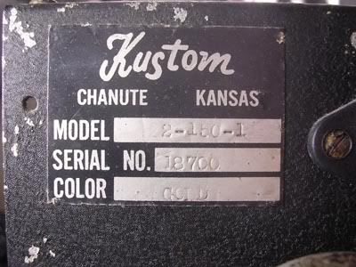
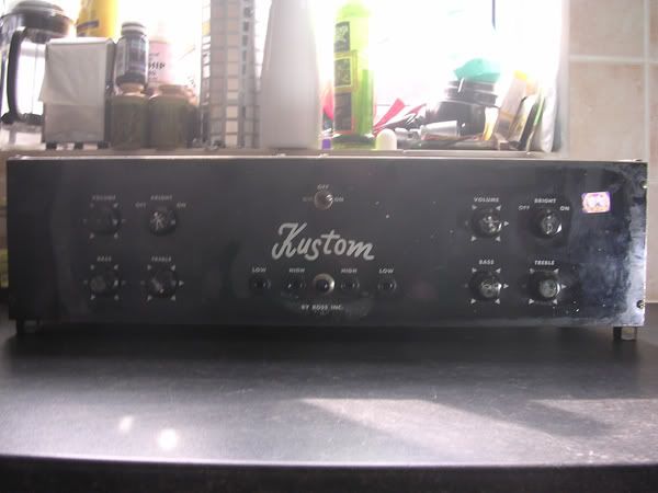
My girlfriend's bass head has been playing up lately. Back panel says Model 2-150-1 - serial number 18700. Beautiful gold tuck and roll with matching cab...
Now, I'm new to amplifier repairs, although I'm competent with electrics and a soldering iron, and experienced in repairing Vox and Farfisa organs. If anyone can sort me out with a schematic for this I could probably work my way through the problem, although all help and pointers gratefully received!
Basically, everything works fine when first powered up, but after it's been running for a while it just fades away to a really quiet, crappy, and lifeless sound.
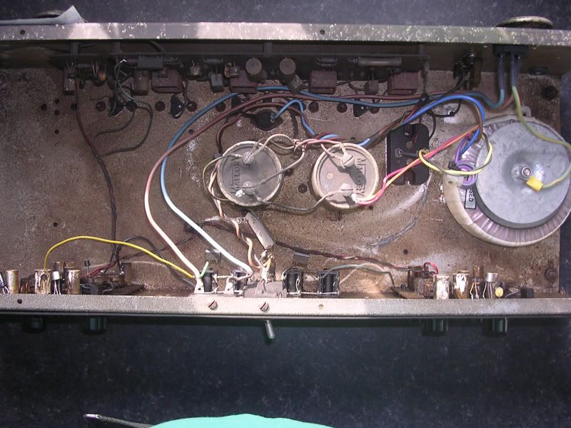
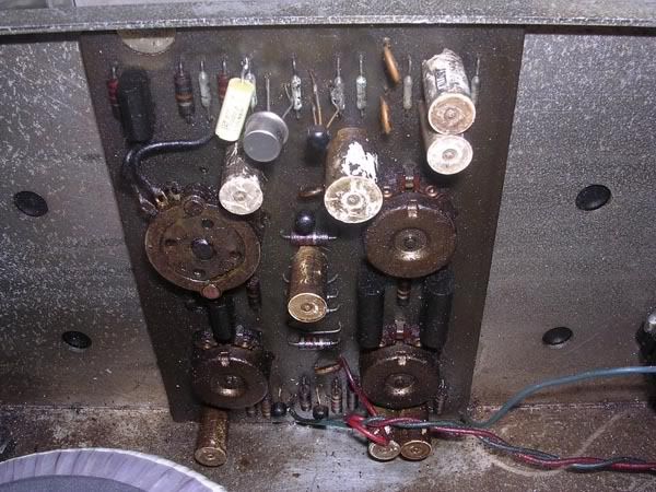
There's nothing obviously recently damaged inside, although the small circuit board to the right of the main board (when viewed from the back) has had the legs of all 4 transistors clipped at some stage before Kate owned it. As we've never come across another one of these, we don't know how this affects the sound, but up until recently it sounded fantastic.
Where these ever imported into the UK? The transformer is newer than the rest of the innards, so we think this was imported and converted. We go to a lot of gigs and neither of us has seen another tuck'n'roll in the UK.
|
|
|
|
| Re: Identifying/repairing [message #8479 is a reply to message #8477] |
Mon, 02 April 2007 22:46   |
rodak
Messages: 516
Registered: October 2001
Location: Georgia
|
Senior Member |
|
|
Hi. Can't help you with the amp repair (someone else will be along shortly with some suggestions, I'm sure).
So you repair Vox and Farfisa organs? Have you seen my website, www.combo-organ.com? Would you be interested in being listed as a repair resource in the UK? Or maybe just join our discussion group to talk about organs.
Robert
www.combo-organ.com
|
|
|
|
| Re: Identifying/repairing [message #8480 is a reply to message #8477] |
Tue, 03 April 2007 07:05   |
 stevem
Messages: 4775
Registered: June 2004
Location: NY
|
Senior Member |
|
|
Hi, here`s my suggestion to narrowing down what the problem could be.
Remove all 4 screws from the bottom of the amp so that when it acts up you can just unplug it a/c wise and just slid it out of the cabinet while its hot because this sounds to me like a semiconductor failing thremaly, also get your self a can of componet freeze spray from an electronics repair supply.
turn the amp on and make note of the thump sound the speakers make at turn on,as this sound is a indication that all is well atleast in the output stage.So with the amp on, play it untill it acts up and then turn it off, wait 5 seconds and turn it back on and listen for that thump sound from the speakers, if thats OK we`ll move on, so if you hear the thump play more to make sure it is still acting up, then quickly unplug the a/c cord and slid the amp out, both channels are boards held to the front panel and stacked on top of one another, its the second, or lower board where I think your problem is.The preamps each use a 14 pin IC chip, and the lower boards IC chip also passes the output thru from the upper preamp.So when you get the amp acting up(which may be faster to induce with a hair dryer)use that freeze spray on that lower boards IC chip and see if the amps power is restored.You can use this hair dyer/ heat up and spray cool down test on any componet in the amp, just do not burn up a good componet with the hair dryer.There is also a FET transistor on one board the could fail also, but if when the amp acts up both channels fail, my first bet would be that lower boards IC chip.Don`t worrie as all the semiconductors can still be had for this 30 plus year old amp.
Also I would check the amps powersupply, since you mentioned that the PT was replaced, the 2 large main supply filters of the differential powersupply should have no more than +40 and -40 volts across them.I forget what these IC chips are rated at, I think 18 volts in the max.GOOD LUCK! and keep us informed on your progress.
|
|
|
|
|
|
|
|
|
|
| Re: Identifying/repairing [message #8487 is a reply to message #8485] |
Tue, 03 April 2007 22:56   |
rodak
Messages: 516
Registered: October 2001
Location: Georgia
|
Senior Member |
|
|
A Transicord, huh? we just had some discussion about it on the combo organ list. You should join up and share your experience. And don't worry about anyone pestering you for repairs and stuff. There are several of us there that are technically capable, and most of the others are pretty gracious and not pushy with their questions.
Yeah, there's a lot of common ground between combo organs and tuck-and-roll enthusiasts. Both feature gaudy colors, all-transistor design, are from the same era, and are equally ignored by most of the modern music scene. Suits me just fine.
Of course, the ultimate merging of the two is the magnificent Kustom Kombo organ.
So yours is a model 2-150-1, but looks like the K200s you have pictured? Someone here may correct me, but those two don't jive. I have a K150, but that only came as a combo amp, I believe. Is yours a metal slant face, or a plexi face? I saw 2-150-1 and thought maybe it was one of those weird Frank model#s that I can never keep track of. Steve mentioned ICs - did the slant-front 150 use ICs, Steve?
www.combo-organ.com
|
|
|
|
|
|
|
|
| Re: Identifying/repairing [message #8490 is a reply to message #8489] |
Wed, 04 April 2007 08:50   |
rodak
Messages: 516
Registered: October 2001
Location: Georgia
|
Senior Member |
|
|
Circuit board mounted on the rear wall of the amp? The preamp boards on my K150 combo are on the front, with the pots soldered to them.
www.combo-organ.com
|
|
|
|
|
|
|
|
| Re: Identifying/repairing [message #8530 is a reply to message #8528] |
Thu, 12 April 2007 12:15   |
chicagobill
Messages: 2006
Registered: April 2003
|
Senior Member |
|
|
Hey guys, if you look closely it appears that the model number is 2-15C-1, which makes it a 200A series head.
I don't know of any 200A series schematics, but the 200A circuits are similar to another series circuit. I can't remember which one, but if you search the archives there was a series of posts on this subject.
Bill
|
|
|
|
|
|
| Re: Identifying/repairing [message #8533 is a reply to message #8531] |
Thu, 12 April 2007 17:26   |
 ace_basement
Messages: 7
Registered: April 2007
Location: London UK
|
Junior Member |
|
|
chicagobill - I can't believe I didn't spot that it was a "C" and not a "0" in the model number! I guess I should look more closely at my own photos!
stevem - the filter cans are 4500MFD 50VDC. And yes, it has 5 TO3s mounted on the base. There are no circuit breakers either side of the on/off switch, just a single 5A fuse on the mains input, mounted to one side of the switch. I'm thinking of putting a panel mounted fuse holder on the rear of the head instead of this fuse as it will be easier to change. Also want to tidy up the mains wiring at the switch and insulate the terminals here so as there's less exposed (mains is 240v here!) Would it be worth doing this for output fuse while I'm at it?
I didn't manage to replicate the problem today - my neighbours were out, so I was able to drive the amp quite hard for nearly an hour but all seemed fine.
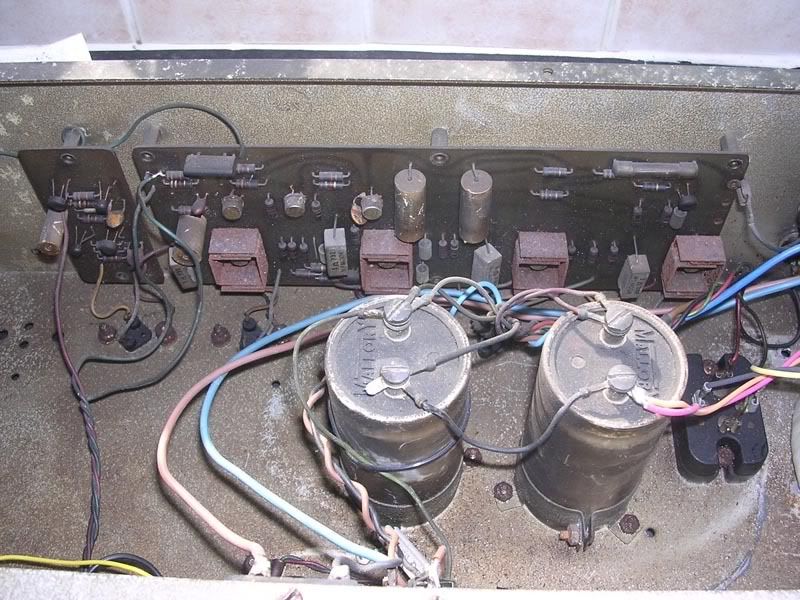
I started trying to remove the pre-amp boards but the knobs are rusted on - as well as the smoke deposits inside there is quite a lot of rust too (from the same incident, maybe?). I have some spray somewhere for rusted bolts, so I'll use that carefully tomorrow, once I've found it... Instead I removed the 2 large filter cans so I could get better access inside. I cleaned them up and the date code 235-6705A magically appeared, so early 1967? All the other Mallory caps were 67## too so I take that as a pretty solid date.
The smaller circuit board mounted on the rear panel is marked "ROSS PC 502". All 4 transistors have had one leg cut - no idea why, but I will replace these. Does anyone know the transitor types I need here?
The larger circuit board at the rear is a PC702. Is this starting to make sense now?
I'm really enjoying getting to grips with this!
|
|
|
|
|
|
|
|
| Re: Identifying/repairing [message #8538 is a reply to message #8537] |
Fri, 13 April 2007 11:57   |
chicagobill
Messages: 2006
Registered: April 2003
|
Senior Member |
|
|
Ace:
I think that the small board to the left of the power amp board is the voltage regulator circuit. In some of the Kustom voltage regulator circuits, they used transistors as diodes, so the cut leads may be correct.
I searched the past threads and it seems that the 400 series schematics are close to the 200A boards.
Bill
|
|
|
|
|
|
| Re: Identifying/repairing [message #8541 is a reply to message #8477] |
Sat, 14 April 2007 08:54   |
hayfever
Messages: 16
Registered: January 2000
Location: Sterling, VA
|
Junior Member
Webmaster |
|
|
I actually have parts of the schematics needed for 200 A series heads. I don't advertise them for sale because I don't have a complete set (I'm missing PC602 for the 200-A4 and I don't know what boards the other heads have in them) or the overview layout schematics that we include with the other sets, but we have sold them to people who needed them through the order form. Just order the B series head and send an email saying you need the A series schematics and provide a list of the PC boards in your amp.
---Hayden Olenik
---Webmaster, VintageKustom.com
|
|
|
|
| Re: Identifying/repairing [message #8542 is a reply to message #8541] |
Sun, 15 April 2007 19:08  |
 ace_basement
Messages: 7
Registered: April 2007
Location: London UK
|
Junior Member |
|
|
OK, so I have rewired the power input side of things so that there are no exposed parts at mains voltage and added a panel mount fuse at the rear of the cabinet. I scoured the aluminium inside and gave it a general cleanup. I remade the solder joints on the PC502 and PC702 boards, and also changed a few capacitors. The grease had long dried up on the TO3s so I fitted new dry thermal conductive mounts.
I've spent hours today trawling through previous posts and things are making much more sense now, especially the stuff about the whole modular system and the common boards between different models.
I have ordered the schematics set from hayfever, and international postage permitting should be enjoying soon. However, if anyone has scans of the 702 and 502 boards they could email that would help me greatly while I wait.
In the meantime the mystery of the voltage regulator board remains unsolved. chicagobill - the cut transistor legs were originally soldered and have traces running from them to elsewhere in the circuit, so it looks like a modification made post manufacture. At the moment I don't know if any other parts have been substituted, but there are no obvious modifications to the traces and no empty holes.
So I'm at the point where I'm going to the amp on and check I haven't made things worse than they were before! I have stevem's words echoing round my tired brain: "When you hook those filters back up make sure you get it right or you will blow one or the other side of the driver and output transistors!" so I'm a little worried now in case my notes were wrong, although I've checked them against the photos above and everything seems right. I think I'll leave it till tomorrow though!
Thanks for all the help, though. It's really making a difference .
|
|
|
|
 VintageKustom.com
 ]
] 

